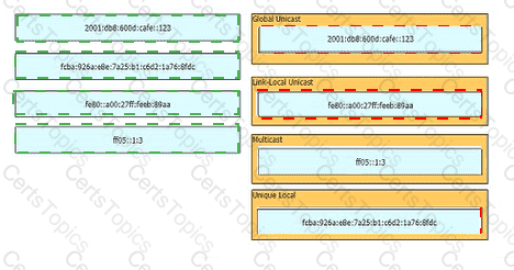
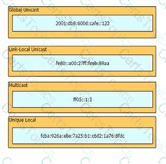
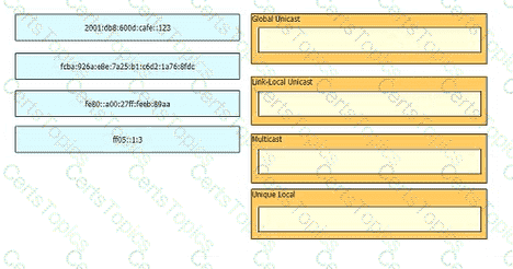
Drag and drop the IPv6 addresses from the left onto the corresponding address types on the right.
How does authentication differ from authorization?
Refer to the exhibit.
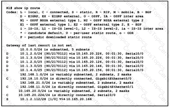
What is the next hop for traffic entering R1 with a destination of 10.1.2.126?
Which QoS traffic handling technique retains excess packets in a queue and reschedules these packets for later transmission when the configured maximum bandwidth has been surpassed?
Copyright © 2021-2026 CertsTopics. All Rights Reserved