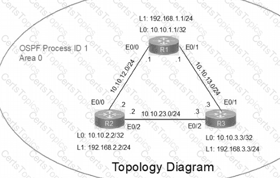
IP connectivity between the three routers is configured. OSPF adjacencies must be established.
1. Configure R1 and R2 Router IDs using the interface IP addresses from the link that is shared between them.
2. Configure the R2 links with a max value facing R1 and R3. R2 must become the DR. R1 and R3 links facing R2 must remain with the default OSPF configuration for DR election. Verify the configuration after clearing the OSPF process.
3. Using a host wildcard mask, configure all three routers to advertise their respective Loopback1 networks.
4. Configure the link between R1 and R3 to disable their ability to add other OSPF routers.
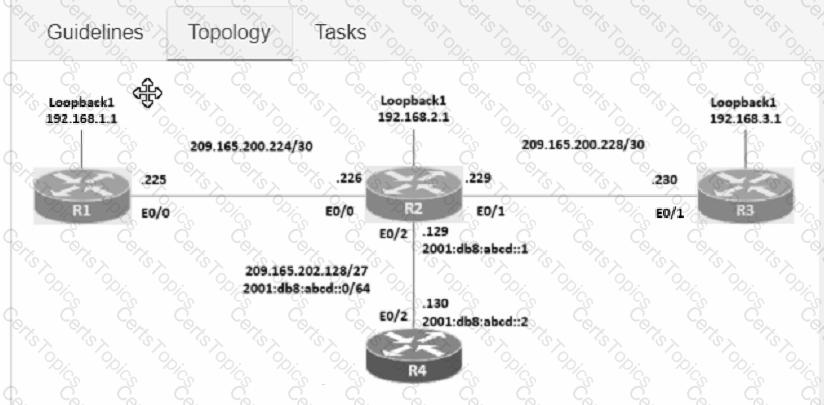
Connectivity between four routers has been established. IP connectivity must be configured in the order presented to complete the implementation. No dynamic routing protocols are included.
1. Configure static routing using host routes to establish connectivity from router R3 to the router R1 Loopback address using the source IP of 209.165.200.230.
2. Configure an IPv4 default route on router R2 destined for router R4.
3. Configure an IPv6 default router on router R2 destined for router R4.
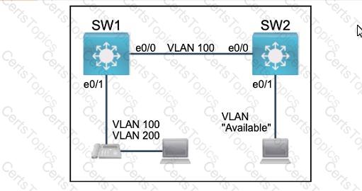
All physical cabling between the two switches is installed. Configure the network connectivity between the switches using the designated VLANs and interfaces.
1. Configure VLAN 100 named Compute and VLAN 200 named Telephony where required for each task.
2. Configure Ethernet0/1 on SW2 to use the existing VLAN named Available.
3. Configure the connection between the switches using access ports.
4. Configure Ethernet0/1 on SW1 using data and voice VLANs.
5. Configure Ethemet0/1 on SW2 so that the Cisco proprietary neighbor discovery protocol is turned off for the designated interface only.
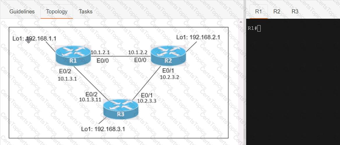
Connectivity between three routers has been established, and IP services must be configured jn the order presented to complete the implementation Tasks assigned include configuration of NAT, NTP, DHCP, and SSH services.
1. All traffic sent from R3 to the R1 Loopback address must be configured for NAT on R2. All source addresses must be translated from R3 to the IP address of Ethernet0/0 on R2, while using only a standard access list named NAT To verify, a ping must be successful to the R1 Loopback address sourced from R3. Do not use NVI NAT configuration.
2. Configure R1 as an NTP server and R2 as a client, not as a peer, using the IP address of the R1 Ethernet0/2 interface. Set the clock on the NTP server for midnight on January 1, 2019.
3. Configure R1 as a DHCP server for the network 10.1.3.0/24 in a pool named TEST. Using a single command, exclude addresses 1-10 from the range. Interface Ethernet0/2 on R3 must be issued the IP address of 10.1.3.11 via DHCP.
4. Configure SSH connectivity from R1 to R3, while excluding access via other remote connection protocols. Access for user root and password Cisco must be set on router R3 using RSA and 1024 bits. Verify connectivity using an SSH session from router R1 using a destination address of 10.1.3.11. Do NOT modify console access or line numbers to accomplish this task.
Copyright © 2021-2026 CertsTopics. All Rights Reserved