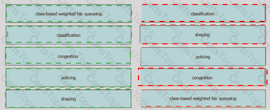
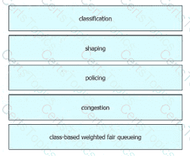
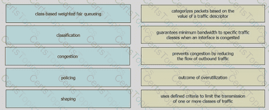
Drag and drop the QoS terms from the left onto the descriptions on the right.
What is a similarity between 1000BASE-LX and 1000BASE-T standards?
Refer to the exhibit.
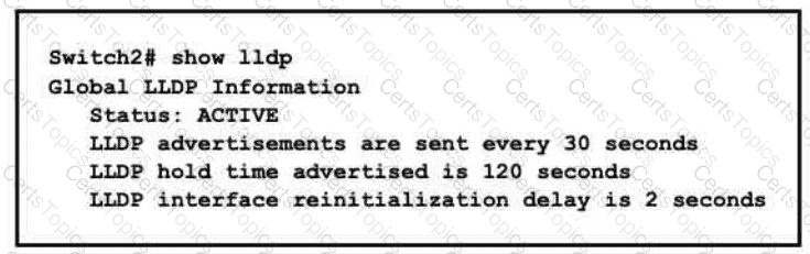
A network engineer must update the configuration on Switch2 so that it sends LLDP packets every minute and the information sent via LLDP is refreshed every 3 minutes Which configuration must the engineer apply?
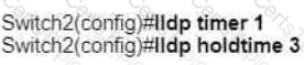
A)

B)

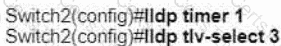
C)
D)
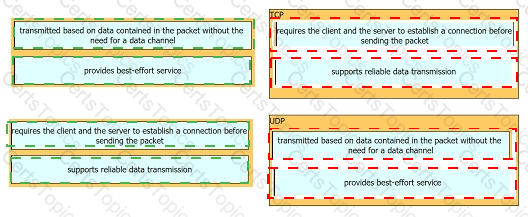
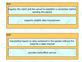
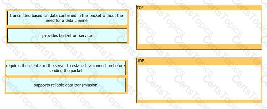
Drag and drop the TCP or UDP details from the left onto their corresponding protocols on the right.
Copyright © 2021-2026 CertsTopics. All Rights Reserved