What is the primary purpose of a First Hop Redundancy Protocol?
Refer to the exhibit.
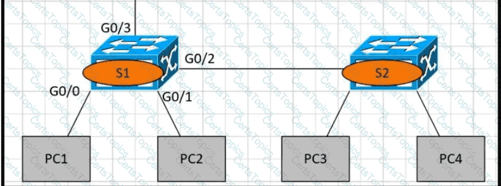
PC1 is trying to ping PC3 for the first time and sends out an ARP to S1 Which action is taken by S1?
Why would VRRP be implemented when configuring a new subnet in a multivendor environment?
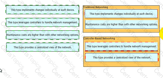
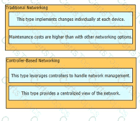
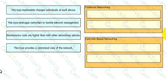
Drag and drop the statements about networking from the left onto the corresponding networking types on the right
Copyright © 2021-2026 CertsTopics. All Rights Reserved