Which dual-band IEEE WLAN standard provides up to 4.8 Gbps of theoretical data rate?
802.11 ac
802.1 lax
802.1 In
802.11 be
The dual-band IEEE WLAN standard that provides up to 4.8 Gbps of theoretical data rate is 802.11 be, also known as Wi-Fi 7. This standard is an amendment to the IEEE 802.11-2020 standard that aims to improve the performance, efficiency, and reliability of WLANs operating in the 2.4 GHz and 5 GHz frequency bands. Some of the key features of 802.11 be include:
The other options are incorrect because they do not provide the same level of data rate as 802.11 be. 802.11 ac, or Wi-Fi 5, supports up to 1.73 Gbps of data rate in the 5 GHz band with 160 MHz channel bandwidth and 256 QAM. 802.11 ax, or Wi-Fi 6, supports up to 9.6 Gbps of data rate in both 2.4 GHz and 5 GHz bands with 160 MHz channel bandwidth, 1024 QAM, and OFDMA, but it is not a dual-band standard as it also supports the 6 GHz band. 802.11 n, or Wi-Fi 4, supports up to 600 Mbps of data rate in both 2.4 GHz and 5 GHz bands with 40 MHz channel bandwidth and 64 QAM. 802.1 lax and 802.1 In are not valid IEEE WLAN standards. References: IEEE 802.11be Extremely High Throughput: The Next Generation of Wi-Fi Technology Beyond 802.11ax, Wi-Fi Timeline, IEEE 802.11-2020
Given the 172.16.0.0 255.255.255.0 IP segment, how many IP addresses can be assigned to host and network devices?
126
6
128
4
Given the IP segment 172.16.0.0 255.255.255.0, we can calculate the number of IP addresses that can be assigned to host and network devices using the following formula:
Number of IP addresses=232−n−2
wherenis the number of bits in the network prefix, which is also the number of ones in the subnet mask. In this case, the subnet mask is 255.255.255.0, which in binary is 11111111.11111111.11111111.00000000. Therefore,n=24. Plugging this into the formula, we get:
Number of IP addresses=232−24−2=28−2=256−2=254
However, this number includes the network address (172.16.0.0) and the broadcast address (172.16.0.255), which cannot be assigned to host and network devices. Therefore, we need to subtract 2 more from the result, which gives us:
Number of IP addresses=254−2=252
This means that there are 252 IP addresses that can be assigned to host and network devices in the IP segment 172.16.0.0 255.255.255.0. The answer option that is closest to this number is A, 126.
References:
1: IP Subnet Calculator2: IP Subnetting - The Basic Concepts - NetworkLessons.com3: Subnetting - Wikipedia
Before routers forward unicast packets, what information is compared with the unicast routing table entries?
The source address of the IP header.
The destination address of the Ethernet header.
The destination address of the IP header.
The source address of the Ethernet header.
The inbound port the packet is received in.
Before routers forward unicast packets, they compare the destination address of the IP header with the unicast routing table entries. This is because routers use the destination IP address to determine the next hop or outgoing interface for the packet. Routers do not care about the source address of the IP header or the Ethernet header, as they are not relevant for forwarding decisions. The inbound port the packet is received in is also not important, as routers use the routing table to make forwarding decisions, not the interface information. Therefore, the correct answer is C. References
Refer to Exhibit.
PC-1 and PC-2 are connected to Interfaces configured as access ports on VLAN 10. All other ports on Switch-1 and Switch-2 are in default settings. Which configuration is required on Doth switches to allow inter-PC communication in the same Broadcast domain?
Option A
Option B
Option C
Option D
In order to allow inter-PC communication in the same broadcast domain, both switches need to have the same VLAN configured on the ports that connect to the PCs and the trunk port that connects to each other. Option B shows the correct configuration for both switches, as follows:
Option A is incorrect because it does not configure the trunk port on Switch-2, which prevents VLAN 10 traffic from reaching Switch-1. Option C is incorrect because it configures the trunk port on Switch-1 with the wrong encapsulation mode (ISL instead of dot1q), which causes a mismatch with Switch-2. Option D is incorrect because it configures the access ports on Switch-2 with the wrong VLAN (20 instead of 10), which isolates PC-2 from PC-1.
References:
1: Layer 2 VLAN Configuration on a Cisco Switch (with Example) - Networks Training 2: VLAN Configuration Commands Step by Step Explained - Computer Networking Notes 3: How To Configure VLANs On the Catalyst Switches - Cisco Community 4: Configure VLAN on Cisco Switch Using Cisco Packet Tracer - TECHNIG
Which statement accurately describes an omnidirectional antenna?
Radiates equal power in all directions in the Elevation Plane.
Radiates almost equal power in all directions in the Vertical Plane.
Radiates more power in a specific angle and less power in others.
Radiates almost equal power in all directions in the Horizontal Plane.
An omnidirectional antenna is an antenna that radiates almost equal power in all directions in the horizontal plane, which is also called the azimuth plane1. This means that the antenna has a 360-degree coverage in the horizontal plane, but a narrow coverage in the vertical plane, which is also called the elevation plane2. An omnidirectional antenna is suitable for indoor environments where the clients are distributed around the access point3. Therefore, statement D accurately describes an omnidirectional antenna. Statements A, B, and C are incorrect because they describe different types of antennas. Statement A describes an isotropic antenna, which is a theoretical antenna that radiates equal power in all directions in both the horizontal and vertical planes. Statement B describes a vertical antenna, which is an antenna that radiates almost equal power in all directions in the vertical plane, but a narrow coverage in the horizontal plane. Statement C describes a directional antenna, which is an antenna that radiates more power in a specific angle and less power in others, creating a focused beam of radio waves. References: 1: Aruba Certified Network Technician (ACNT) Study Guide, page 872: Aruba Certified Network Technician (ACNT) Study Guide, page 883: Aruba Certified Network Technician (ACNT) Study Guide, page 89. : Aruba Certified Network Technician (ACNT) Study Guide, page 87. : Aruba Certified Network Technician (ACNT) Study Guide, page 88. : Aruba Certified Network Technician (ACNT) Study Guide, page 89.
What is part of the 5 GHz band?
Channel 12 and 13
U-NII 5
Channels 149 to 161
Channel 14
The 5 GHz band is a radio frequency band used for Wi-Fi communications. It has a higherdata bandwidth than the 2.4 GHz band, but a shorter range and less penetration through walls. The 5 GHz band is divided into several sub-bands, each with a different set of channels. One of these sub-bands is the U-NII-3 band, which covers the frequency range from 5725 MHz to 5850 MHz. This sub-band contains 24 non-overlapping channels, numbered from 149 to 172. Channels 149 to 161 are part of the 5 GHz band and can be used for Wi-Fi communications. Channels 165 and 169 are restricted to indoor use only, and channel 173 is not allowed in some regions. Channels 12, 13, and 14 are not part of the 5 GHz band, but belong to the 2.4 GHz band, which has a different set of channels and regulations. U-NII-5 is not a valid sub-band name, but a proposed extension of the 5 GHz band to include the frequency range from 5925 MHz to 7125 MHz. This extension is not yet approved or implemented, and therefore not part of the 5 GHz band. References: List of WLAN channels, What’s the Difference Between 2.4 and 5 GHz Wi-Fi (and Which Should I Use)?, What is the difference between 2.4 GHz, 5 GHz, and 6 GHz wireless frequencies?
Refer to Exhibit.
To which protocol does the header belong?
User Datagram Protocol
Transmission Control Protocol
802.11 Wi-Fi
Ethernet Protocol
Internet Protocol
The header in the exhibit belongs to the User Datagram Protocol (UDP), which is a transport layer protocol that provides connectionless and unreliable data delivery. UDP header consists of four fields: Source Port, Destination Port, Length, and Checksum. The Source Port and Destination Port fields identify the endpoints of the communication, and are 16 bits each. The Length field specifies the total length of the UDP datagram, including the header and the data, and is also 16 bits. The Checksum field is used to verify the integrity of the UDP datagram, and is optional in IPv4 but mandatory in IPv6. The Checksum field is also 16 bits.
The other options are incorrect because:
B. Transmission Control Protocol (TCP) is another transport layer protocol that provides connection-oriented and reliable data delivery. TCP header has more fields than UDP header, such as Sequence Number, Acknowledgment Number, Window Size, etc. TCP header is at least 20 bytes long, while UDP header is only 8 bytes long.
C. 802.11 Wi-Fi is a set of standards for wireless local area networks (WLANs). 802.11 Wi-Fi header is different from UDP header, as it contains fields such as Frame Control, Duration, Address 1, Address 2, Address 3, etc. 802.11 Wi-Fi header is at least 24 bytes long, while UDP header is only 8 bytes long.
D. Ethernet Protocol is a data link layer protocol that defines the physical and logical characteristics of a wired network. Ethernet header is different from UDP header, as it contains fields such as Destination MAC Address, Source MAC Address, EtherType, etc. Ethernet header is 14 bytes long, while UDP header is 8 bytes long.
E. Internet Protocol (IP) is a network layer protocol that provides logical addressing and routing for data packets. IP header is different from UDP header, as it contains fields such as Version, Internet Header Length, Type of Service, Total Length, Identification, Flags, Fragment Offset, Time to Live, Protocol, Header Checksum, Source IP Address, Destination IP Address, etc. IP header is at least 20 bytes long, while UDP header is 8 bytes long. References:
What is considered a Layer 2 component?
Router
Switch
Transceiver
UTP cable
A switch is a device that operates at the data link layer (Layer 2) of the OSI model. It is responsible for forwarding frames based on the MAC addresses of the source and destination devices. A switch can also perform media access control, VLAN tagging, QoS, and other Layer 2 functions. A router, on the other hand, operates at the network layer (Layer 3) and routes packets based on their IP addresses. A transceiver is a device that converts electrical signals to optical signals and vice versa, and operates at the physical layer (Layer 1). A UTP cable is a type of twisted pair cable that is also used at the physical layer to transmit data. References: Data link layer - Wikipedia, Data Link Layer | Layer 2 | The OSI-Model, What is Layer 2? - Definition from Techopedia, An Overview of Layer 2 Ethernet – What is it and why does it matter?
Which protocol provides logical addressing used for routing messages across the network towards their destination?
Internet Protocol
Transmission Control Protocol
Wired Ethernet
Link Layer Discovery Protocol
The protocol that provides logical addressing used for routing messages across the network towards their destination is the Internet Protocol (IP). IP is a network layer protocol that assigns a unique numerical identifier to each device on a network, called an IP address. IP addresses are used to identify the source and destination of data packets, and to determine the best path to deliver them. IP is a connectionless and best-effort protocol, meaning that it does not guarantee the delivery, order, or integrity of the packets. IP relies on other protocols, such as TCP, to provide reliable and orderly data transfer.
The other options are incorrect because:
B. Transmission Control Protocol (TCP) is a transport layer protocol that provides reliable and orderly data delivery by establishing a connection between devices and providing error-checking and retransmission mechanisms. TCP does not provide logical addressing or routing functions, but it uses IP addresses to identify the endpoints of a connection.
C. Wired Ethernet is a data link layer protocol that defines the physical and logical characteristics of a wired network, such as cable types, frame formats, and MAC addresses. MAC addresses are used to identify the physical devices on a network segment, but they are not used for routing messages across the network. Ethernet does not provide logical addressing or routing functions, but it relies on IP to do so.
D. Link Layer Discovery Protocol (LLDP) is a data link layer protocol that allows devices to discover and advertise information about themselves and their neighbors on a network, such as device type, capabilities, port configuration, and VLAN membership. LLDP does not provide logical addressing or routing functions, but it can help network administrators to troubleshoot and optimize the network topology. References:
What are the nonoverlapping channels for Wi-Fi communications in the 2.4 Ghz band?
1,6,11,andl3
1,6, and 11
1.7,11, and 14
1,7, and 13
In the 2.4 GHz band, only channels 1, 6, and 11 are non-overlapping, meaning that they do not share any frequency spectrum with each other. This makes them the preferred channels for Wi-Fi networks to minimize interference with other devices that use the same band, such as Bluetooth, microwave ovens, cordless phones, etc. Using non-overlapping channels also allows for better performance and throughput, as devices on the same channel have to contend for the medium and avoid collisions. Channels 2 to 5 overlap with channel 1, channels 7 to 10 overlap with channel 6, and channels 12 and 13 overlap with channel 11. Channel 14 is not allowed in most countries and regions, and it also overlaps with channel 11. Therefore, using any of these channels would cause interference with the non-overlapping channels and degrade the network quality. The 2.4 GHz band has a total of 14 channels, each with a bandwidth of 22 MHz and a center frequency separated by 5 MHz. However, the actual frequency range used by each channel is wider than 22 MHz, as the signal spreads out due to modulation. This means that adjacent channels partially overlap with each other, and only channels that are 25 MHz apart or more are completely non-overlapping. The following table shows the center frequency and frequency range of each channel in the 2.4 GHz band:
Table
Channel
Center frequency (MHz)
Frequency range (MHz)
1
2412
2401-2423
2
2417
2406-2428
3
2422
2411-2433
4
2427
2416-2438
5
2432
2421-2443
6
2437
2426-2448
7
2442
2431-2453
8
2447
2436-2458
9
2452
2441-2463
10
2457
2446-2468
11
2462
2451-2473
12
2467
2456-2478
13
2472
2461-2483
14
2484
2473-2495
As shown in the table, only channels 1, 6, and 11 have a 25 MHz separation between their center frequencies, and therefore do not overlap with each other or any other channel. This makes them the best choice for Wi-Fi communications in the 2.4 GHz band. References:
How many addresses does the 255.255.252.0 provide?
16384
32768
8192
1024
The subnet mask 255.255.252.0 is equivalent to the CIDR notation /22, which means that 22 bits are used for the network prefix and 10 bits are used for the host part. To calculate the number of addresses that this subnet mask provides, we can use the formula2n−2, wherenis the number of bits in the host part. In this case,n=10, so the number of addresses is210−2=1024−2=1022. The subtraction of 2 is because the first and the last addresses are reserved for the network identifier and the broadcast address, respectively. Therefore, the subnet mask 255.255.252.0 provides 1022 usable addresses for hosts, plus 2 reserved addresses, for a total of 1024 addresses.References:IP Subnet Calculator,How many host addresses are available on the network … - ITExamAnswers
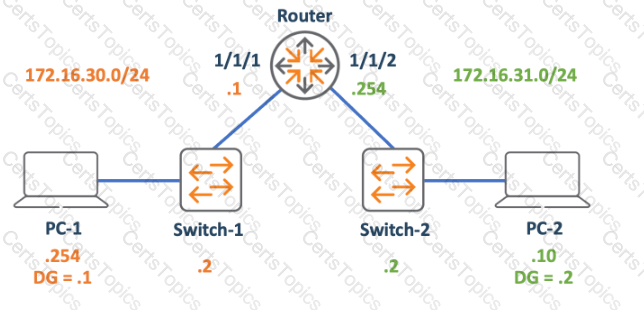
Refer to Exhibit.
The PCs are not able to successfully establish bidirectional communication. What change must you deploy to enable the communication between PC-1 and PC-2?
change PC-1 's default gateway to 172.16.30.2
change PC-1's IP address to 172.16.30.10
change the Router's 1/1/1 interface IP to 172.16.30.254
change PC-2's default gateway to 172.16.31.254
The PCs are not able to successfully establish bidirectional communication because they are on different subnets and their default gateways are not configured correctly. The default gateway is the IP address of the router interface that connects to the same subnet as the PC. The default gateway allows the PC to send packets to destinations outside its own subnet. In this case, PC-1 and PC-2 are on the 172.16.30.0/24 and 172.16.31.0/24 subnets respectively, and the router interfaces are 172.16.30.254 and 172.16.31.254 respectively. Therefore, the correct default gateway for PC-1 is 172.16.30.254 and the correct default gateway for PC-2 is 172.16.31.254. Changing PC-2’s default gateway to 172.16.31.254 will enable the communication between PC-1 and PC-212 References:
Which characteristic allows switches to mitigate collisions?
The switches support VLANs that segment the collision domains.
The switches use L3 protocols that eliminate collisions.
The switches' ports are independent collision domains.
The switches have proprietary features that help eliminate collisions.
A collision occurs when two or more devices try to transmit data at the same time on a shared medium, such as a bus or a hub. Collisions degrade network performance and cause data loss. Switches mitigate collisions by creating separate collision domains for each port. This means that each port can transmit and receive data without interfering with other ports. Switches also use full-duplex communication, which allows simultaneous transmission and reception of data on each port, further reducing the chances of collisions. VLANs and L3 protocols do not affect collisions, as they operate at different layers of the network model. Proprietary features are not a general characteristic of switches, and may not be compatible with other vendors’ switches. References: Aruba Certified Network Technician (ACNT) | HPE Aruba Networking, Aruba Documentation Portal
What are the differences between Local-based and Server-based management? (Select two.)
server-based management cannot talk to the device's control plane, local-based can
in local-based, the managed device is a client, while in server-based it is a server
local-based management can use the device's console port, server-based cannot
local-based management requires an on-premises network management appliance
server-based management can monitor multiple devices at once, local-based cannot
Local-based management refers to managing a network device directly from the device itself, using tools such as console port, web interface, or command-line interface. Server-based management refers to managing a network device remotely from a centralized server, using tools such as Windows Admin Center, System Center, or Azure Arc123. The differences between these two types of management are:
References:
1: Cloud vs Server: Learn the Key Differences and Benefits - Parallels 2: Windows Server management overview | Microsoft Learn 4: 5 Benefits of Server-Based Local Access Networks for Small … - Versatech 3: What is Windows Admin Center | Microsoft Learn
What is the goal of the TCP three-way handshake?
To notify the destination who the originator is.
To acknowledge the reception of the segments.
To establish a reliable, flow-controlled connection.
To notify the number of segments that will be sent.
The TCP three-way handshake is a process that is used in a TCP/IP network to create a connection between a client and a server. It involves the exchange of three packets: SYN, SYN-ACK, and ACK. The goal of the TCP three-way handshake is to establish a reliable, flow-controlled connection between the two endpoints. This means that the connection is able to ensure that the data is transmitted without errors, losses, or duplications, and that the data is sent at a rate that both sides can handle.
The TCP three-way handshake works as follows:
After the TCP three-way handshake is completed, the connection is established and the data transfer can begin.
References: The answer can be verified by using the following resources:
Which message is an example of Broadcast communication?
DHCP offer
ICMP echo
HTTP Get
ARP Request
Broadcast communication is the distribution of audio or video content to a dispersed audience via any electronic mass communications medium, using the electromagnetic spectrum (radio waves), in a one-to-many model1. A broadcast message is a message that is sent to all endpoints on the network, regardless of their address or identity2. An example of a broadcast message is an ARP request, which is used to find the MAC address of a device that has a specific IP address3. An ARP request is sent to the broadcast address of the network, which is usually the last address in the subnet (e.g., 192.168.1.255 for a /24 network). All devices on the network receive the ARP request and check if their IP address matches the one in the request. If so, they reply with their MAC address to the sender of the ARP request. If not, they ignore the request4. Therefore, an ARP request is an example of broadcast communication, while the other options are not. A DHCP offer is a message that is sent by a DHCP server to a specific client that requested an IP address5. An ICMP echo is a message that is sent by a device to test the connectivity and latency to another device. An HTTP Get is a message that is sent by a web browser to request a web page from a web server. These messages are not broadcast, but rather unicast, meaning they are sent to a single destination. References: 1: Broadcasting - Wikipedia 2: Broadcast communication network - Wikipedia 3: [Address Resolution Protocol - Wikipedia] 4: [How ARP Works - Cisco] 5: [DHCP - Wikipedia] : [Ping (networking utility) - Wikipedia] : [Hypertext Transfer Protocol - Wikipedia] : : resolution/13718-5.html : : :
Refer to Exhibit.
The PC is sending a message to the server. Which devices have performed Layer 2 encapsulation by the time the message arrives at the server? (Select two.)
PC
Server
Router
switch-2
Switch-1
Layer 2 encapsulation is the process of adding a header and a trailer to the data coming from the upper layer (Layer 3) before sending it over the physical medium. The header and the trailer contain information such as source and destination MAC addresses, error detection, and protocol type. The devices that perform Layer 2 encapsulation are usually switches, bridges, or network interface cards (NICs). In the given network diagram, the PC is sending a message to the server. The PC first adds a Layer 2 header and trailer to the data and sends it to Switch-1. Switch-1 performs Layer 2 encapsulation again before forwarding it to the router. The router operates at Layer 3 and does not perform Layer 2 encapsulation. It only removes the Layer 2 header and trailer, checks the destination IP address, and forwards the packet to the next hop. The packet then reaches Switch-2, where Layer 2 encapsulation occurs again before it is sent to the server. The server also performs Layer 2 de-encapsulation by removing the header and trailer and passing the data to the upper layer. Therefore, the devices that have performed Layer 2 encapsulation by the time the message arrives at the server are Switch-1 and Switch-2. References: Understanding Data Link Layer Encapsulation, How Data Encapsulation & De-encapsulation Works?, HDLC Protocol and Encapsulation method Explained
Why do clients run the Address Resolution Protocol (ARP)?
To discover the destination address of the Layer 3 header of IP packets.
To discover the source address of the Layer 3 header of IP packets.
To discover the destination address of the Layer z header that encapsulates IP packets.
To discover the source address of the Layer z header that encapsulates IP packets.
ARP is a protocol that maps an IP address to a MAC address, which is the physical address of a device on a network. ARP is necessary because the software address (IP address) of the host or computer connected to the network needs to be translated to a hardware address (MAC address). Without ARP, a host would not be able to figure out the hardware address of another host. ARP works by sending a broadcast message to all devices on the network, asking for the MAC address of the device that has a specific IP address. The device that has that IP address replies with its MAC address, and the sender stores this information in its ARP cache for future use. The sender then uses the MAC address as the destination address of the Layer 2 header that encapsulates the IP packet. The Layer 2 header is also known as the data link layer header, which is responsible for delivering the packet to the correct device on the same network. The Layer 3 header is also known as the network layer header, which is responsible for routing the packet to the correct network. Therefore, the correct answer is C, because ARP is used to discover the destination address of the Layer 2 header that encapsulates IP packets1234 References: What Is Address Resolution Protocol (ARP)? - Fortinet, Address Resolution Protocol - Wikipedia, ARP (Address Resolution Protocol) explained - Study-CCNA, Aruba Certified Network Technician Exam HPE3-U01 Actual Questions
Copyright © 2014-2024 CertsTopics. All Rights Reserved