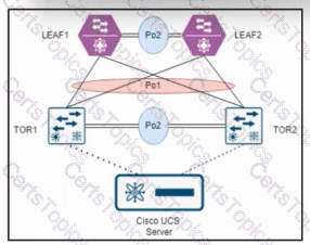
In Cisco data center and cloud-scale designs, adouble-sided vPC(also called vPC-to-vPC) is used when both ends of a Layer 2 port channel are formed by a pair of switches that operate as vPC peers. In this model:
On the aggregation or leaf side, two switches (in this case,LEAF1 and LEAF2) form a vPC domain with a vPC peer-link and keepalive.
On the access or ToR side, two switches (in this case,TOR1 and TOR2) must also form their ownvPC domainwith a peer-link and vPC keepalive.
The port-channel that interconnects the two vPC domains is then configured as a vPC on both sides, creating a vPC-to-vPC topology.
The problem statement specifies thatLEAF1 and LEAF2 are already configured as vPC peers. For a double-sided vPC to work, the other side (TOR1 and TOR2) must also behave as a single logical entity for the downstream Cisco UCS server and for the upstream vPC connection towards LEAF1 and LEAF2. This is only achieved when TOR1 and TOR2 are configured as vPC peers with:
A vPC domain ID
A vPC peer-link between TOR1 and TOR2
vPC member port-channels towards LEAF1 and LEAF2 and towards the Cisco UCS server
Therefore, the next required step is to configure avPC between TOR1 and TOR2.
Evaluation of the options:
Option A, “Add all the switches to the fabric,” is generic and not specific to vPC configuration. It does not address the technical requirement to form a vPC domain on the ToR side.
Option B, “Configure peering between LEAF1 and LEAF2 and TOR1 and TOR2,” is incorrect because vPC peering is only configured between the two switches that form each vPC domain (LEAF1–LEAF2 and TOR1–TOR2), not across all four switches together.
Option C, “Configure MSTP between TOR1 and TOR2,” is not required for establishing a double-sided vPC. vPC designs rely on the vPC control plane and the peer-link, not on spanning-tree between the vPC peers for normal operation.
Option D, “Configure a vPC between TOR1 and TOR2,” correctly describes configuring TOR1 and TOR2 as a vPC pair (vPC domain with peer-link), which is the mandatory step to create a double-sided vPC topology with LEAF1 and LEAF2.